Imagine you’re troubleshooting a circuit and need to know if a battery is dead or a power supply is working. You grab your voltmeter, connect the probes, and stare at the display. Only then do you realize you’re not entirely sure what you’re seeing. This moment is exactly where knowing how to read a voltmeter scale becomes essential. Whether you’re using an analog meter with a sweeping needle or a digital model with a crisp numerical readout, accurate interpretation is the key to diagnosing electrical issues, verifying circuit operation, and ensuring safety.
This guide breaks down exactly how to read any voltmeter scale step by step. You’ll learn the differences between analog and digital meters, how to set the correct range, and the common mistakes that lead to false readings. By the end, you’ll confidently measure voltage in any setting.
Choose the Right Voltmeter Type for Your Needs
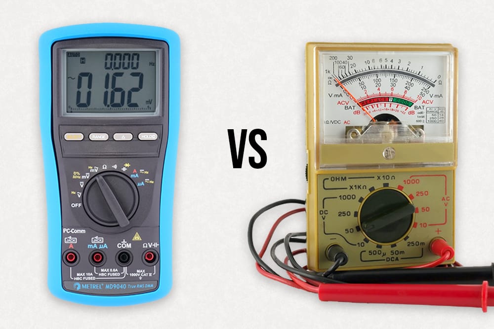
Before reading a scale, understand which type of voltmeter you’re using. The two main types differ significantly in display, precision, and reading method.
Analog Voltmeters Use Needle and Scale Movement
Analog voltmeters use a needle that moves across a printed scale. You must interpret its position based on range settings and scale divisions. These meters excel at observing voltage trends and are often used in educational settings. However, they’re prone to parallax error and require manual range selection. The mirror strip behind the scale helps eliminate viewing angle mistakes.
Digital Voltmeters Show Direct Numerical Readouts
Digital voltmeters display voltage as a number on a screen, eliminating guesswork. They often include auto-ranging, polarity detection, and overload warnings. Digital models offer higher accuracy and easier reading but depend on battery power. The display shows the numerical value, unit, polarity, and mode indicators.
| Feature | Analog Voltmeter | Digital Voltmeter |
|---|---|---|
| Readout | Needle and scale | Numeric digits |
| Accuracy | Moderate, user-dependent | High, ±0.5% typical |
| Range Selection | Manual | Manual or auto-ranging |
| Best For | Learning, observing fluctuations | Precision, field use |
When to Use Each Type
Use an analog voltmeter when teaching voltage concepts, monitoring fluctuating signals, or working in environments where digital screens may fail. Use a digital voltmeter for precise measurements, fast diagnostics, or when working with low voltages where small changes matter.
Set Up Your Voltmeter Correctly Before Measuring
Proper setup ensures safe and accurate readings. Skipping this step leads to false measurements or equipment damage.
Select AC or DC Mode Matched to Your Circuit
Voltage comes in two forms: direct current and alternating current. DC voltage is constant and comes from batteries, power supplies, and electronic circuits. Look for symbols like ⎓, VDC, or “–” on the meter. AC voltage alternates direction and powers household outlets. Use the ~ or VAC setting. Always match the meter mode to the circuit type. Measuring AC on DC mode gives incorrect readings and may damage sensitive circuits.
Pick the Correct Voltage Range
Choose a range higher than the expected voltage to avoid overload. For a 1.5 V AA battery, use the 2 V or 20 V range. For a 9 V battery, select 10 V or 20 V. For household outlets at 120 V AC, use the 200 V or 600 V AC range. On analog meters, exceeding the range pegs the needle to the right. On digital meters, you’ll see “OL” or “1” indicating overload. If this happens, increase the range and retest.
Read an Analog Voltmeter Scale Accurately
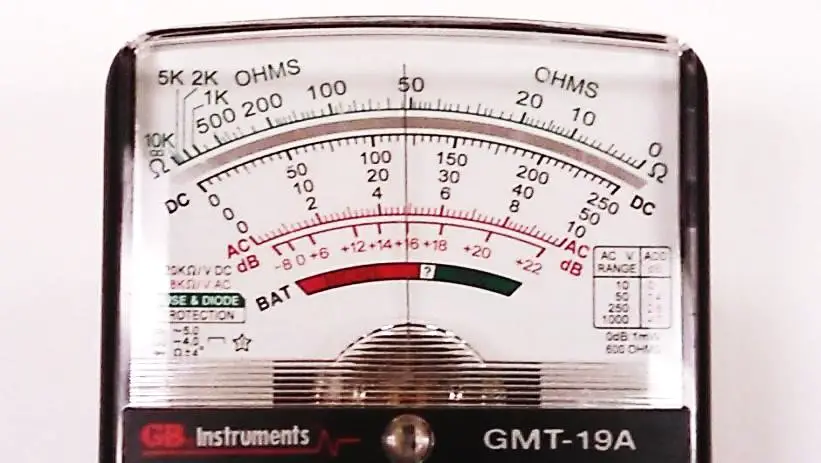
Analog voltmeters require calculation and careful observation. Mastering this skill builds a deeper understanding of voltage measurement.
Identify the Scale and Selected Range
Analog scales are usually linear and labeled with numbers like 0, 5, 10, 15, or 30. The selected range determines what these numbers represent. On a 30 V range, the full scale equals 30 volts. On a 15 V range, the same physical scale equals 15 volts. On a 3 V range, the needle reaches full scale at 3 volts. Always check the range selector switch before reading.
Calculate Value Per Division
Divide the full-scale voltage by the number of divisions to find the value per mark. On a 30 V range with 30 divisions, each division equals 1 V. On a 15 V range with 30 divisions, each division equals 0.5 V. On a 3 V range with 30 divisions, each division equals 0.1 V. This calculation is critical for accurate reading.
Read the Needle Position Correctly
Count the divisions from zero to the needle tip. For example, if the range is 15 V and the needle is 5 divisions past 10 V, with each division worth 0.5 V, the reading equals 10 V plus (5 × 0.5 V) = 12.5 V. On a 3 V range with the needle at 18 divisions, the reading equals 18 × 0.1 V = 1.80 V. Estimate between marks when needed.
Avoid Parallax Error When Reading the Scale
Viewing the needle from an angle causes parallax error. The needle appears to point to different values. To fix this, look straight on at the scale. Use the mirror strip behind the scale and adjust your position until the needle aligns with its reflection. When aligned, your reading is accurate.
Report Readings with Proper Precision
Significant digits should reflect the scale’s resolution. On a 30 V range with 1 V per division, report as 18.0 V (implies ±0.5 V). On a 15 V range with 0.5 V per division, report as 12.5 V. On a 3 V range with 0.1 V per division, report as 1.80 V. This communicates how precise your measurement is.
Use a Digital Voltmeter Display Effectively
Digital voltmeters simplify reading but still require attention to detail.
Understand the Display Layout and Symbols
A digital display shows the numerical value, unit (V, mV, kV), polarity (negative sign if leads are reversed), and mode indicators (AC ~, DC ⎓, HOLD, OL). A reading of 1.58 on the 20 V DC range equals 1.58 volts. Always check what the display is telling you.
Interpret Decimal and Units Correctly
Misreading decimals leads to big errors. 0.158 V equals 158 mV. 15.8 V equals 15,800 mV. 0.001 V equals 1 mV. Always check the unit symbol and decimal point before recording your reading.
Know Your Meter’s Digits and Display Limits
Most digital multimeters are 3½-digit, meaning they can display up to 1999 counts. The “½” means the first digit can only be 0 or 1. Hence, ranges are 2 V, 20 V, 200 V, not 10 V or 100 V. On the 20 V range, the maximum reading is 19.99 V. Anything higher shows “OL” for overload.
Connect Your Voltmeter Safely to Circuits

Improper connection can damage circuits or cause injury.
Always Connect in Parallel Configuration
Connect the voltmeter in parallel with the component being measured. Place the red probe on the high-potential side (positive). Place the black probe on the low-potential side (negative or ground). This measures the voltage drop across the component without interrupting current flow. Never connect in series, as this breaks the circuit and gives incorrect readings.
Handle Polarity Correctly to Avoid Damage
Reversing probes on digital meters shows a negative value, indicating reversed polarity. On analog meters, the needle deflects below zero, which can damage the meter. If the needle moves left of zero, reverse the leads immediately.
Troubleshoot Common Voltmeter Reading Errors
Even experienced users make mistakes. Knowing how to spot and fix them improves accuracy.
Needle Not at Zero? Adjust Mechanical Zero
Analog meters can drift. If the needle doesn’t sit at zero with no voltage applied, use the mechanical zero screw (usually below the scale) to adjust it. Do this before every use for best results.
OL on Display? Check Your Range Setting
“OL” means voltage exceeds the selected range. Switch to a higher range (for example, from 20 V to 200 V). Never exceed the meter’s maximum voltage rating.
Fluctuating Readings? Check Your Connections
Unstable readings often come from loose probe contact, poor circuit connections, or a failing power source. Press probes firmly onto terminals. Clean corroded contacts. Verify power supply stability.
Low or Zero Reading? Verify Your Setup
If you get zero, check the battery in digital meters. Confirm function and range settings. Test leads on a known voltage source like a battery. A dead battery or wrong setting is often the culprit.
Apply Advanced Voltage Measurement Techniques
Once comfortable with basic readings, use the voltmeter for deeper circuit analysis.
Measure Voltage Drop Across Components
To check if a component is working, power the circuit. Place the red probe on the input side and the black probe on the output side. Read the voltage difference. A blue LED should show approximately 2.66 V drop. A much lower or higher value indicates a problem. This technique helps identify bad connections, failing components, or incorrect biasing.
Perform Differential Voltage Measurements
In floating circuits with no ground reference, measure voltage between two non-grounded points. Use a high-input-impedance meter (at least 10 MΩ) to avoid loading the circuit. This ensures accurate readings in isolated systems like battery-powered devices.
Detect High Resistance Through Voltage Drop
A higher-than-expected voltage drop across a wire or connector indicates excessive resistance, often due to corrosion or loose connections. Measure the drop across a switch or fuse. If the drop exceeds 0.1 to 0.3 V, clean or replace the component. This method is faster than resistance testing under load.
Follow Essential Voltmeter Safety Practices
Electricity demands respect. Safety comes first.
Inspect Equipment Before Every Use
Check probe insulation for cracks or burns. Ensure leads are not frayed. Verify battery level in digital meters. Damaged equipment increases shock and short-circuit risk.
Never Exceed Voltage Ratings
Every voltmeter has a maximum input voltage (for example, 600 V CAT II). Exceeding it can destroy the meter, cause arcing or fire, and result in electric shock. Always match the meter to the circuit.
Use PPE in High-Voltage Areas
When working with mains voltage or high-energy circuits, wear insulated gloves and safety glasses. Use tools rated for the voltage. Keep one hand behind your back to reduce shock path through your chest.
Test Outlets Safely Before Measuring
Before using a multimeter on an outlet, use a non-contact voltage tester first. Confirm power is on and wires are live. This prevents accidental contact with live terminals.
Maintain and Calibrate Your Voltmeter
Regular upkeep ensures long-term accuracy.
Clean and Store Your Meter Properly
Wipe the case with a dry, soft cloth. Store in a cool, dry place away from dust and moisture. Keep probes coiled and protected. Avoid dropping or exposing to extreme temperatures.
Calibrate Annually for Accuracy
Over time, meters drift. Calibration corrects this. Compare readings to a known standard like a precision voltage source. Adjust internal trimmers on analog meters or follow the digital calibration procedure. Recommended annually or after physical shock. Document calibration dates for professional or industrial use.
Frequently Asked Questions About Reading Voltmeter Scales
How do I read an analog voltmeter scale?
Identify the selected range (for example, 3 V, 15 V, or 30 V). Calculate the value per division by dividing the full-scale voltage by the number of divisions. Count divisions from zero to where the needle points. Estimate between marks for greater precision. Use the mirror strip to avoid parallax error.
What’s the difference between AC and DC on a voltmeter?
DC measures direct current from batteries and power supplies (look for ⎓ or VDC). AC measures alternating current from household outlets (look for ~ or VAC). Always match the mode to your circuit type to get correct readings and prevent damage.
How do I calculate voltmeter scale divisions?
Divide the full-scale voltage by the total number of divisions on the scale. For a 30 V range with 30 divisions, each mark equals 1 V. For a 15 V range with 30 divisions, each mark equals 0.5 V. For a 3 V range with 30 divisions, each mark equals 0.1 V.
Why does my voltmeter show OL?
OL means overload. The voltage exceeds your selected range. Switch to a higher range setting. For example, if reading 9 V on the 2 V range, switch to the 20 V range.
What does a negative reading mean on a digital voltmeter?
A negative reading indicates reversed polarity. Your red and black probes are connected backward. Swap the probes to get a positive reading. The negative sign doesn’t mean the circuit is faulty.
How do I choose the right voltage range?
Select a range higher than the expected voltage. For a 1.5 V battery, use 2 V or 20 V. For a 9 V battery, use 10 V or 20 V. For household outlets, use 200 V or 600 V. Starting high prevents overload, then switch lower for better resolution.
Key Takeaways for Reading Voltmeter Scales
Knowing how to read a voltmeter scale is more than just reading numbers. It’s about understanding circuits, avoiding errors, and working safely. Whether you’re using an analog meter with its needle and mirror or a digital model with auto-ranging, the principles remain the same. Select the right mode (AC or DC), set the proper range higher than expected voltage, connect correctly in parallel, and interpret carefully based on the scale divisions. Practice these steps with various circuits to build confidence. With time, reading voltage becomes second nature, and your voltmeter becomes a powerful tool for diagnosing, verifying, and mastering electrical systems.