Essential Components for Building a Scale

Every digital scale relies on four essential components working together: the load cell, signal conditioner, microcontroller, and display. Understanding each part ensures your build works reliably.
Load Cell: The Weight Sensor
The load cell is the heart of your scale. It converts physical force (weight) into an electrical signal. When you place an object on the scale, the load cell bends slightly. The more weight applied, the greater the deformation. This tiny deflection changes the resistance in a strain gauge, which is a thin metal foil bonded to the load cell’s surface.
Most DIY projects use a strain gauge load cell because it’s accurate, affordable, and easy to interface. These come in various capacities (1kg, 5kg, 10kg). For this build, we use a 5kg single-point load cell, ideal for small to medium loads.
Identifying Load Cell Wires
Your load cell likely has four colored wires. The standard configuration includes Red for excitation voltage (V+), Black for ground (V-), White for output signal (S+), and Green for output signal (S-). Some models include a sixth wire (often blue or yellow) for EMI shielding, which should be connected to ground. Always check your load cell’s datasheet because wire colors vary by manufacturer.
Signal Conditioning with HX711 Module
The raw signal from the load cell is extremely weak, measured in millivolts, and full of electrical noise. That’s where the HX711 module comes in. It acts as a complete signal conditioner with three key functions.
The module provides amplification by boosting the microvolt-level signal. It offers filtering by removing electromagnetic interference (EMI). It performs analog-to-digital conversion (ADC) by outputting digital data. Because the HX711 includes an ADC, it sends clean digital signals directly to the Arduino, no analog pins needed. This simplifies wiring and improves accuracy.
Arduino: The Processing Unit
The Arduino (Uno or Nano) serves as the brain of your scale. It reads the processed weight data from the HX711, applies calibration values, and calculates the final weight. Then it sends that number to the display. Arduino is ideal for beginners due to its simplicity, strong community support, and ready-made libraries like HX711.h.
LCD Display for Weight Readout
A 16×2 character LCD shows the weight in real time. Connected to the Arduino via I2C or standard GPIO pins, it provides a clear readout in grams or kilograms. An I2C adapter reduces wiring clutter. Just four wires are needed: VCC, GND, SDA, and SCL.
Mechanical Setup for Your Scale
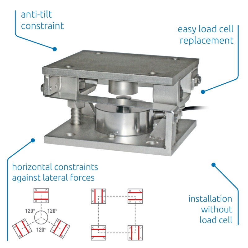
To transfer weight accurately, the load cell must be mounted between two rigid platforms. The bottom platform serves as a fixed base made from wood, acrylic, or metal. The top platform acts as the movable load-bearing surface.
Use screws or adhesive to attach the load cell so only vertical force is applied. Avoid side loads or twisting, which damage the strain gauge. For a 5kg cell, ensure all materials are sturdy but lightweight.
Pro Tip: Test mechanical stability by pressing gently on the platform. It should move slightly without wobbling.
Wiring the Load Cell to HX711
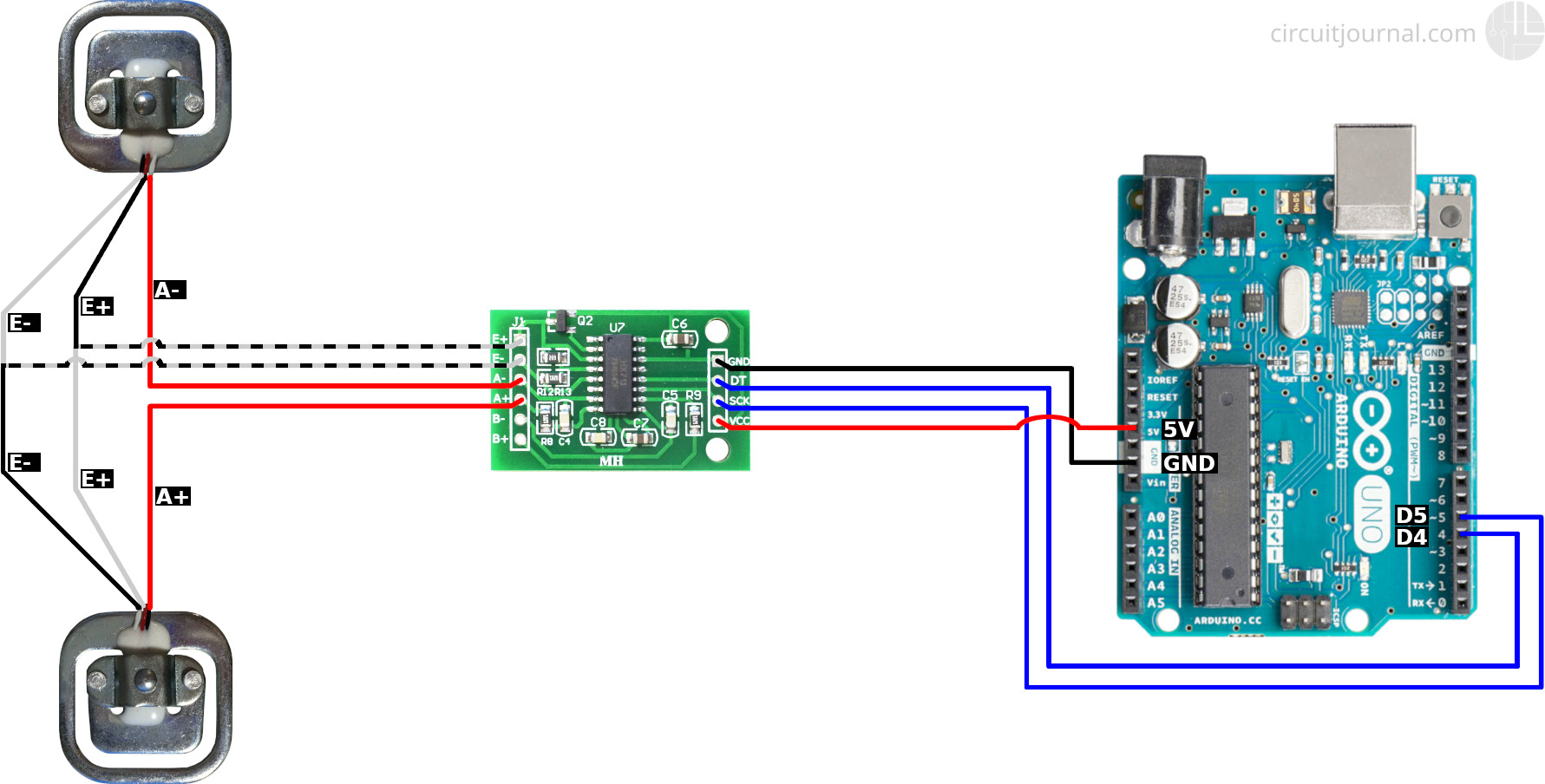
Connect the load cell wires to the HX711 module’s input terminals (E+, E-, A+, A-) as follows.
The Red wire (V+) connects to E+. The Black wire (V-) connects to E-. The White wire (S+) connects to A+. The Green wire (S-) connects to A-. If your load cell has a shield wire, connect it to the power ground (GND) on the Arduino side.
Warning: Reversing E+ and E- may damage the load cell. Double-check polarity before powering on.
Connecting HX711 to Arduino
Now link the HX711 to the Arduino using these connections.
VCC connects to 5V on Arduino. GND connects to GND on Arduino. DT (Data) connects to Digital Pin 3. SCK (Clock) connects to Digital Pin 2. DT and SCK allow serial communication between modules, and these pins can be changed in code if needed.
Attaching the LCD Display
For a clean setup, use an I2C-enabled 16×2 LCD. The VCC pin goes to Arduino 5V. The GND pin goes to Arduino GND. The SDA pin goes to Arduino A4. The SCL pin goes to Arduino A5.
If using a non-I2C LCD, connect D4 through D7, RS, EN, and RW pins to digital outputs on the Arduino. This requires more wiring and library configuration.
Calibrating Your Scale
Before displaying correct weights, the system needs calibration. This step determines two critical values: the offset (the raw reading when nothing is on the scale) and the scale factor (which converts raw data to grams or kilograms).
Calibration Steps
First, open Arduino IDE and install the HX711 library via Library Manager. Next, upload the calibration sketch. Then, open Serial Monitor at 9600 baud. Place the scale on a level surface with no load and wait for a stable reading. This becomes your offset value.
Place a known weight (for example, 500g) on the platform. Adjust the scale_factor in code until the displayed weight matches the actual weight. Record the final scale factor and offset value for use in your weighing code.
Programming the Weighing Function
Once calibration is complete, upload the weighing code to the Arduino. This code uses the calibration values you recorded to display accurate weight measurements in real time. The Serial Monitor will show readings like 500.00g for a 500g weight or 1000.00g for a 1kg weight.
Troubleshooting Common Scale Problems
If your scale displays erratic readings or negative values, check the wiring connections first. Ensure the load cell is properly mounted and not subjected to lateral forces. Verify that the calibration values are correctly entered in your code.
If the display shows no reading, confirm that the LCD is properly connected and the I2C address matches your library configuration. Loose connections at any point in the circuit can cause intermittent or absent readings.
Frequently Asked Questions About Building a Scale
What load cell capacity should I choose for a DIY scale?
For most DIY projects measuring small to medium objects, a 5kg load cell provides the best balance between sensitivity and capacity. If you need to weigh heavier items, consider a 10kg or 20kg load cell. Remember that higher capacity cells are less sensitive to very light weights.
Can I use a different microcontroller instead of Arduino?
Yes, you can use other microcontrollers like ESP32 or Raspberry Pi. However, Arduino is recommended for beginners because of its simple programming environment and extensive library support. The HX711 library works seamlessly with Arduino’s ecosystem.
Why does my scale show negative readings?
Negative readings typically occur when the load cell wires are connected incorrectly. Check that the White (S+) and Green (S-) wires are not reversed. Also verify that your calibration offset was taken with nothing on the scale platform.
How do I improve the accuracy of my DIY scale?
To improve accuracy, ensure the scale is on a perfectly level surface. Use a known weight for calibration that is close to the weights you plan to measure most often. Allow the load cell to stabilize for a few seconds before taking readings. Shield the wiring from electrical interference.
Do I need to recalibrate the scale over time?
Recalibration may be needed if you notice drift in readings over time or after moving the scale. Temperature changes can affect load cell sensitivity. Periodic recalibration with a known weight ensures continued accuracy.
Final Thoughts on Building Your Own Scale
Building a digital scale is an excellent hands-on project that teaches you about sensors, signal processing, and embedded programming. The key to success lies in proper mechanical mounting of the load cell and accurate calibration. Take your time with the wiring and double-check all connections before powering on.
Once your scale is working, you can expand the project by adding features like tare functionality, unit conversion (grams to ounces), or even wireless connectivity. The foundation you build here opens doors to more advanced electronics projects. Start simple, get it working, then add complexity as you learn.